Distinguishing natural from induced fractures in image logs
Introduction
Induced tensile fractures are the most common and easily visible induced fractures observed in image logs and core. Induced fractures are easily distinguished from natural fractures in core by visually examining fracture surface morphology and the geometric relationships between the core and the fracture shape, origin flaw and propagation path (Kulander et al; 1979, 1990). Individual fractures cannot be identified positively as natural or induced based solely on the fracture trace in an image log.
However, the origin of a group of fractures is determinate from image log data because natural fractures and induced fractures have different geometries relative to the borehole. If breakouts are present and if the natural fractures formed in a stressfield significantly different from the present-day stressfield, then the orientation of the fractures relative to the breakouts provides an additional (though less rigorous) criteria for distinguishing the two types of fractures.
This page provides some simple rules for using image logs to differentiate natural fractures of all types from induced tensile fractures and to distinguish induced fractures that form after passage of the bit from petal and petal-centerline fractures which form ahead of the bit.
The Rules
These rules apply to sections of the wellbore where the in-situ stresses maintain a constant orientation relative to the wellbore. This page does not directly address induced shear fractures; however, Rule 1 is applicable to them.
Rule 1: The stacking rule
Induced fractures that do not completely cut the wellbore have a consistent orientation and tend to appear at the same azimuth in the image, but natural fractures with a consistent orientation that do not completely cut the wellbore appear at different azimuths in the image.
Rule 2: The aperture rule
Induced tensile fractures are always open; natural fractures may be open or partially to completely mineralized or gouge-filled.
Rule 3: The continuity rule
The continuity of a fracture trace is not an indication of its origin. Both natural and induced fractures can cross the entire wellbore or can be confined to a particular lithology.
Rule 4: The orientation rule
The orientation of a fracture relative to the in-situ (present-day) stress is not an indication of its origin.
Rule 5: The breakout rule
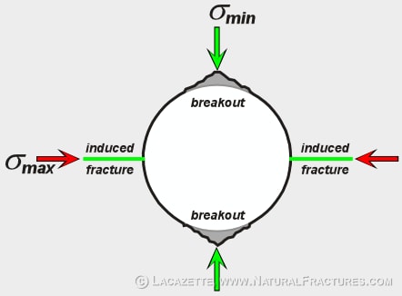
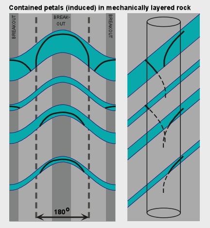
Hydraulically induced fractures form in, and tend to be restricted to, the tensile quadrants of the wellbore wall, which are 90° from the breakouts. Petal fractures form ahead of the bit in what will become the compressive quadrants (where breakouts develop); poorly developed petal fractures tend to be restricted to the compressive quadrants.
Rule 6: The symmetry rule
Individual natural fractures are often symmetrically developed on opposite sides of the borehole; petal and centerline fractures are nearly always symmetrical; but hydraulic fractures are usually asymmetrically developed.
Orientations of breakouts and induced fractures
In most of the world one of the three principal stresses is oriented vertically, which requires the other two to be oriented horizontally. However, inclined stressfields do occur, especially in tectonically active areas. Breakouts form in response to the minimum and maximum stress that are oriented perpendicular to the wellbore.
Induced fractures tend to form perpendicular to the least principal stress, so that well-developed, borehole-parallel induced fractures form when σ3 (the minimum principal stress) is oriented perpendicularly to the borehole. Hydraulic induced fractures tend to be inclined to the wellbore when σ3 is inclined to the wellbore, although they may not form perpendicular to σ3 in this case.
Figure 1. Schematic cross-section of a wellbore showing the orientation of breakouts and induced hydraulic and centerline fractures relative to the borehole perpendicular in-situ earth stress components. Broken-out (missing) material shown in dark gray. Induced fractures tend to form perpendicular to the least principal stress, so that well-developed, borehole-parallel induced fractures form when σ3 (the minimum principal stress) is oriented perpendicularly to the borehole.
Petal fractures, centerline fractures, and petal-centerline fractures
Petal, centerline, and petal-centerline fractures form ahead of the bit during both coring and normal drilling operations. They normally extend beyond the final borehole diameter so that they can usually be correlated between core and image logs. The direction of fracture propagation is always downhole.
Petal fractures ("petal" as in "flower petal") are the curved fractures that begin on the edge of the wellbore and curve parallel to the centerline fracture in the center of the core. Petal fractures form just ahead of the bit and are due to excessive bit weight. They always accurately mark the compressive quadrant of the wellbore wall because they form immediately ahead of the bit.
Centerline fractures propagate ahead of the bit, probably within approximately 1/2 meter of the bottom of the hole. They are driven by a combination of mud pressure and bit-induced stresses. The orientation of centerline fractures gives the orientation of the least principal stress. However, the location of a centerline fracture is not an accurate guide to the tensile quadrant because centerline fractures propagate ahead of the bit and do not accurately track the center of the well.
Petal-centerline fractures are petal fractures that grow to become a centerline fracture or that join with a centerline fracture.
Figure 2a. Photos of 4 inch (10cm) diameter core of the sandstone reservoir rock from an oil well in West Texas, U.S.A. showing petal fractures. Petal fractures can form in isolation whether or not a centerline fracture is present.
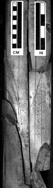
Figure 2b. Photos of 4 inch (10cm) diameter core of the sandstone reservoir rock from an oil well in West Texas, U.S.A. showing petal-centerline fractures. The centerline fracture is the continuous fracture that bisects the core. Petal fractures that grow to become a centerline fracture or that join with a centerline fracture are termed petal-centerline fractures.
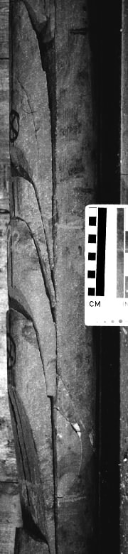
Figure 2c. Approximately 6.5 feet (2 meters) of continuous core. Note how the centerline fracture maintains a constant azimuthal orientation but gently wanders from side to side, and does not stay centered on the core. The petal fractures consistently originate in the compressive quadrant, propagate toward the centerline fracture, and curve smoothly into it. Handling fractures in this core were caused by flexure of the core barrel when it was laid on the rig floor; some are marked with an H. Note that the handling fractures abut (terminate against) the petal and centerline fractures, proving that the handling fractures are younger.

Figure 3. CBIL images of oil well in limestone from Oklahoma, U.S.A. showing petal, centerline and petal-centerline fractures.
The images show the amplitude ultrasonic pulses reflected from the wellbore wall by a rotating transducer. The images are compressed in depth (the vertical dimension).
Figures 3a & 3b show respectively unrolled (map view) and rolled (synthetic core view) of CBIL images showing a centerline fracture that nucleates in a group of petal fractures, propagates downcore, and exits the core at a petal fracture that is concave uphole and propagated from the center of the core outwards. Petal fractures that are concave uphole are relatively rare. Figure 3c is a detailed view of the origin of the centerline fracture but the look direction is opposite that of Figure 3a. Compare with Figure 2b.
Figure 3a. 4016–4036 ft (1,224.1–1,230.2 m)
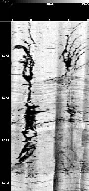
Figure 3b. 4016–4036 ft (1,224.1–1,230.2 m)
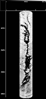
Figure 3c. 4012–4032 ft (1,222.9–1,229.0 m)
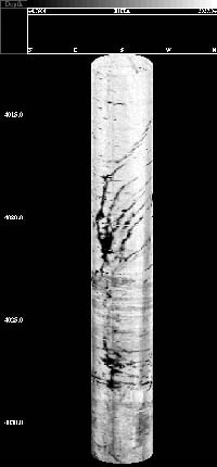
Figure 3d. 4015–4031 ft (1,223.8–1,228.7 m)
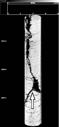
Schematic log images and cross-sections illustrating identification criteria
Natural fractures are distinguished from induced tensile fractures in image logs using gross geometric criteria expressed as the six rules above. The most fundamental principle: induced fractures are geometrically related to the wellbore but natural fractures are not.
Key principles:
- The extent of a fracture is not an indication of its origin — both natural and induced fractures can cross the entire wellbore or be confined to a particular lithology.
- The orientation of a fracture relative to the in-situ (present-day) stress is not an indication of its nature.
- Symmetrical fractures are usually pre-drill (natural fractures and petal/centerline fractures are often symmetrically developed across the wellbore).
- Asymmetrical fractures are usually post-drill (hydraulic fractures form after passage of the bit and opposite sides of the wellbore are mechanically decoupled).
Figure 4a. Figure 4a. The well has randomly caught four wellbore-parallel fractures, which are color coded. Projections of the fractures are shown on the bottom of the core view at right to facilitate visualization. If these fractures were induced, they would appear at the same azimuth and there would be 180 degrees between each trace. These fractures have no particular relationship to the breakout orientations because they are natural.
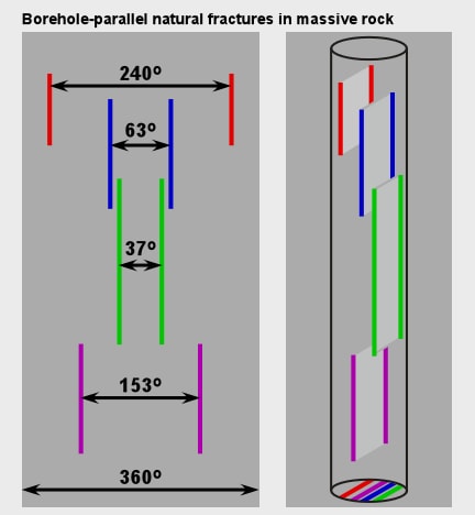
Figure 4b. Figure 4b. Fractures only developed in the blue lithology. In the image log view the yellow sine waves show fracture orientations, the black lines show the fracture traces. All of the fractures have the same orientation. The fracture traces are present at different azimuths in the wellbore because the well randomly samples a population of small fractures. These fractures have no particular relationship to the breakout orientations because they are natural.
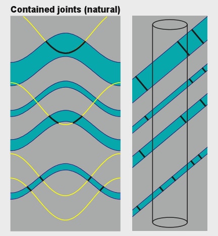
Figure 4c. Figure 4c. The stratigraphy, orientation of bedding, and fracture orientations are identical in this figure and Figure 4b. Because these fractures are induced they form at a consistent azimuth in the wellbore. The lowermost fracture is the same in Figure 4b and this figure. If natural fractures were present in this orientation in this well, it would not be possible to determine if that particular fracture was natural or induced. These fractures are induced so they develop only in the tensile quadrant of the wellbore, at 90 degrees to the breakouts.
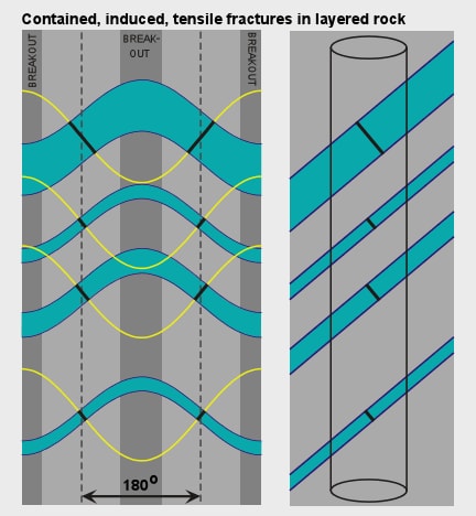
Figure 4d. Figure 4d. Schematic log images showing wellbore parallel (left) and inclined (right) post-drilling induced fractures. The fractures are only developed in the tensile quadrant of the wellbore, at 90 degrees to the breakouts. A common interpretation error is to incorrectly correlate two independent fracture traces (red sine wave). Note that two independent fracture segments can coincidentally lie on the correct sine wave (green sine wave).
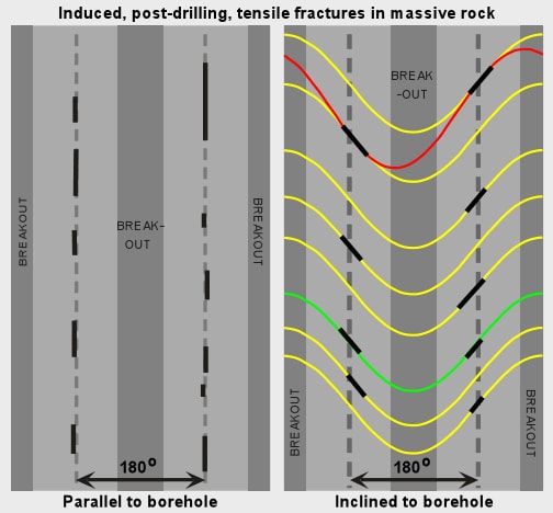
Figure 4e. Figure 4e. Petal fractures are induced, form in the compressive quadrants, and have a consistent relationship to the breakouts. However, the centerline fracture formed ahead of the bit and may wander around all over the image, although on average a well-developed centerline fracture will closely track the center of the tensile quadrant. Petal fractures are curved so that they cannot be fit by a sine wave (colored sines).
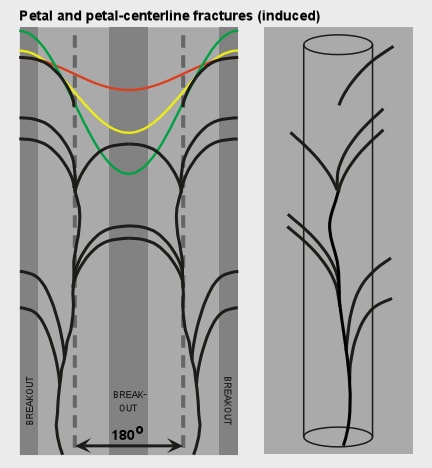
Figure 4f. Figure 4f. Petal fractures may only develop in one lithology.
Quiz
STOP! DON'T READ THE ANSWER UNDER THE IMAGE!
Look at this image and try to decide on your own: Are they natural or are they induced?
False-color STAR image (red: amplitude, green: microtopography, blue: resistivity) from an oil well in granite.
Figure 5. Figure 5. False-color STAR image (red: amplitude, green: microtopography, blue: resistivity) from an oil well in granite. Depths in meters below an arbitrary subsurface datum.
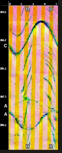
Answer
Image shows two natural fractures (A) and well-developed induced fractures arranged in parallel rows on opposite sides of the wellbore (B). Breakouts are absent. Fracture C is less easy to interpret because it crosses the entire borehole and is oriented parallel to the smaller induced fractures above and below it. The induced fracture immediately above C crosses into the compressive quadrant of the borehole, indicating (but not proving) that fracture C is also induced. These induced fractures appear to be post-drill, probably hydraulic, fractures rather than petal fractures because they are asymmetrically developed and nucleated in two parallel rows on opposite sides of the borehole rather than nucleating on one side of the well and propagating towards the centerline. Note that induced fractures abut both natural fractures, which shows their relative ages.